Friday, November 11, 2016

First Practical Example

Well I have been working on my ESP Widget device and finally have a practical application up and running.  Here it is up and running on my test widget...


What it does is rotate the display between consecutive segments of Interstate 45 as it passes through Houston.  For each segment is will display the average speed and the NeoPixel will be changed to a color corresponding to the speed.

It is actually driven by a backend application that scrapes the public traffic site and formats the data for display on the widget.  Perhaps in time I will publish this as an example.

Wednesday, November 2, 2016

Developing With MicroPython on the Wemos D1 Mini

Just a quick post about the utility I created to edit files on my Wemos D1 Mini using the AMPY file utility by Adafruit.  I wrote a small wrapper GUI around the command line app to make working with files easier.


The source code can be found here...

     https://github.com/joewez/AmpyFileManager

Monday, October 24, 2016

Introducing the ESP Widget

Well after much wrangling with the firmware code, I finally have a version that seems to be stable.  With this milestone out of the way, I feel it is time to show you my latest work.  I call it the ESP Widget.


It's a small USB-powered device that constantly retrieves information via Wifi and displays it on a small OLED screen.  It is built around a Wemos D1 Mini ESP8266 board and runs an application written in MicroPython.

Here is the actual schematic for all of the connections:


The case was 3D printed of course, which was designed in OpenSCAD.


It was a tight fit, and the wiring was a bit tricky, but with some tweezers it seemed to work fine,


The final piece of the puzzle was the firmware to make it work.  I will make another post about that.

Friday, October 21, 2016

Programming the Wemos D1 Mini

I have found that there are two viable choices for development (for me) with the Wemos D1 Mini... either the Arduino development environment or MicroPython.

ESP8266 Arduino
Having experience with Arduino is a big help when getting started using that approach.  They have already done alot of the work for you here http://www.esp8266.com/ and all you need to do is add

     http://arduino.esp8266.com/stable/package_esp8266com_index.json

to your board manager and then you can import the libraries.


There is an extensive list of examples, especially dealing with Wifi and Internet communications.

I'm really impressed with the Arduino support for my D1 Mini.  I can access all of my shields (except my neopixel shield) and the code is all C.  It works well and I have to say it would be my main development route if it were not for a couple of reasons.


  1. Deep Code Nesting.
    The libraries of course build on one another, and sometimes you have problems that originate, deep in the library code... which may or may not be C.  It could be C++ which is different.  I was getting errors at high level calls, but was unable to trace it all the way down to where I could understand the problem and fix or work around it.
  2. Difficult Debugging
    Similar to above, there were many reasons why it was hard to get something original big and complex working.


MicroPython
I am not a Python programmer, but am very interested in learning it because of all of its positive attributes.  As I am just starting out, I am copying code more than I am writing it, but I have to say it is a really nice language.

First of all, it is a much higher level of programming... so it takes less code to do the same things.  Instead of layer after layer of C code, it equates to one or two layers of Python and that's it.  Neat.

The second nice thing is that it is REALLY Python 3.0.  As I program the microcontroller, I am learning the "big" Python language as well. Bonus.

Finally, I am finding Python FUN!  After years of C# and VB.NET programming, I am enjoying the simplicity, the readability and the power of Python.


Thursday, October 20, 2016

Another Diversion

I guess it is in my nature to have more than one project going at a time.  While I tend to obsess, and focus on a single project during the duration, sometime I have to back away and do something else.

So, I have put off the final steps of building my Cherry 3D Printer, to work on another fun project.  This one is related to the Arduino, but is more closely described as an ESP8266 obsession.  This little chip is like a little Arduino with built-in WiFi capabilities and it only costs a few dollars.  It's great.

Wemos D1 Mini
There are actually many ESP8266 boards available, but the one I have settled on is the Wemos D1 Mini.  It's cheap at around $4 shipped and it has a nice ecosystem of shields that make it easy to experiment with.

There are shields for...

  • Lipo Battery powering and charging
  • SD Card shield
  • Relay Shield
  • Neopixel Shield
  • Button Shield
  • etc...
 

MicroPython
The best part about the ESP8266 is it's ability to be programmed in Python!  I am talking about MicroPython of course,  This great piece of software is an amazingly complete implementation of Python 3 for a microcontroller!

I will be documenting my experiments and projects coming up.  Exciting!


Wednesday, August 17, 2016

Differences From The Basic Cherry 3D Printer

Here are some of the changes that I am having to face when trying to build my own version of the printer.

Base Material
About the only locally source of MDF is from the Home Depot hardware store.  I chose to use a 1/2"inch thickness which works out to 12.7mm.  I was able to buy a 2ft x 2ft piece for about $6.  This would be sufficient for the base and any extra bracing I might want to add.


Base Construction
Instead of gluing the base together, I chose to use small wood screws.  Only a few are needed in a few key spots to hold it all together well.


Smooth Rod Lengths
While I was eventually able to source the correct lengths of smooth rod for the printer, I decided to use a set of different lengths to see how they affected the design and construction.  For the X-Axis smooth rods, we have to adjust the width of the base to accommodate for the difference from the 17.5 cm.  With different Y-Axis smooth rods, our bed length will change.  Finally, any differences in the Z-Axis smooth rods have little impact on the overall design.


Thursday, July 21, 2016

Finally Ready To Begin

Well the smooth rods and linear bearing I ordered off of AliExpress arrived.  So I finally can begin the construction of my version of the Cherry printer.

I took some time to sort out the parts last night and for a "bare-minimum" printer, there were still a lot of parts to keep track of.  I have already identified a need for a picture of all the parts for the documentation.  So much to do...

Here are some of the initial tasks I will have to tackle first...

  1. Sort and document all the parts that will be used in the build
  2. Cut the pieces for the printer base
  3. Perform, record and document the bipolar conversion hack on 4 28BYJ-48 motors.
    1. Remove Cover
    2. Cut center trace
    3. Cut or de-solder red wire.
    4. Add extension wire
    5. Replace cover
  4. Cut the motor holes in the top deck of the printer base
    1. Z-Axis Motor Holes (ends)
      1. Assemble X-Axis carriage and X-Axis smooth rods with the X-Axis end pieces.
      2. Insert Z-Axis smooth rods into Z-Axis motor holders.
      3. Place the whole X-Axis assembly onto the Z-Axis smooth rods
      4. Measure or trace the position of the Z-Axis motors and their holders.
      5. Cut the motor holes as accurately as you can
    2. Y-Axis Motor Hole (center)
      1. Center the Y-Axis Motor Holder
      2. Trace the hole position
      3. Cut the motor hole
  5. Perform, record and document the initial assembly of the RAMPS 1.4 board
    1. (Research)
    2. Mount on the Mega
    3. Mount each stepper stick module
    4. Apply heat sinks to stepper stick
  6. Start a Build Manual on Google Docs
While I intend to cite every resource that I use to get this printer going, I will try to keep the document rather self-contained and complete.  By documenting each step... as I do it, I hope to build something that others will find helpful.

Well let me get to it... :-)

Monday, July 11, 2016

Cherry Printer Update

Well after about a month of shopping online and waiting, I still have critical pieces of the printer missing for the build. :-(  The pieces I am talking about are the linear shafts and bearings. Everything else I have ready to go.

In the interim, I have taken to using SketchUp to plan the build as well as to use for illustrations for the build document.  Here are some sample shots of what I have mocked up so far...


There are certain aspects of the build that I need to keep as flexible as possible.
  • Varying Smooth Rod Lengths
  • Optional Z-Axis Frame for Better Bracing
  • Different Build Plate Sizes And Types
  • Different Bowden Extruders


Wednesday, June 15, 2016

Initial Cost Projections

While the availability of most of the components is pretty high, there are some parts that will be hard to come by.

Smooth Rods (8mm)
Six of these are needed to for the three axis that will be traversed during printing.  While the design calls for 4 x 17.5cm rods and 2 x 22cm rods, coming by these dimensions may be difficult.  So I am prepared to substitute and use other lengths.

Threaded Rod (M5)
The metric M5 threaded rod will also have to be sourced.  Threaded rods in my location are all based on English units which makes a difference in the configuration of the printer.

The rest of the parts should be readily source-able...

DescriptionPriceQuantityTotal
12 - LM8UU Linear bearings$8.081$8.08
2 - GT2 Pulleys + GT2 Belt$5.241$5.24
10 - 624 Bearings$2.761$2.76
Bowden Extruder Drive + NEMA 17 Stepper$17.501$17.50
PTFE Tube$2.001$2.00
Arduino Mega + RAMPS 1.4 + 4xA4988$22.791$22.79
28BYJ-48 Stepper Motor$1.654$6.60
3 - Endstop Switches$2.691$2.69
Hotend$9.991$9.99
$77.65

Monday, June 13, 2016

My Next Obsession

I have been feeling the bug for a new project, and I think I have one.  I think I would like to build my own 3d-printer based on the design found here.


The Cherry 60 Euro 3D Printer is a very simple design that lends itself to being relatively easy to build and very low cost.  The speed will certainly be the most limiting factor.  It uses very cheap 28BYJ-48 stepper motors, which are slow and don't provide as much torque as a Nema 17 stepper motor.


But they are cheap, easy to find and can be hacked for better performance.  Which leads me to my main goals for this project.


  1. Inexpensive (Under $100)
  2. Easy To Build
  3. Functional
So stick around, as I will try to document the process here.  More to come.

Tuesday, June 7, 2016

What's Been Going On

Sorry for the long hiatus.

I've been mostly busy with my 3d printer.  Looking for models to print, designing new objects with TinkerCAD and OpenSCAD, and flying my quadcopters when I get a chance,

The weather here has been pretty nasty this summer so far, with rain making it wet and humid.  All together not very enjoyable to be outside.

OctoPrint Setup

One of the cooler things I have done recently is to setup an OctoPrint server to run my 3d Printer,


I am using my Raspberry Pi Model B+ to run the server software.  It was a pretty simple setup which only took about 30 minutes.  Luckily, my Logitech webcam worked with no problems and this has allowed me time lapse all of my prints.  Here are just a couple...


Anyway, I will try to make posts more often... letting you know what I'm up to!


Thursday, February 25, 2016

The Culprit

After much consternation the last few days, I have finally solved the riddle of my extrusion problems.  The culprit...


The K-Extruder that I am using, is slipping AND chewing, which is causing barely any filament to be extruded.


While I have been raising the temperature higher and higher, the lower viscosity of the PLA was not helping it extrude any more than above.

Again, I found the solution to the problem when the "rocker arm" actually broke.  While I had to fix the arm to print, I used a small clamp to keep the bearing pressed against the filament.  That's when I realized my problem.  The extrusion problem immediately went away and I was printing at 205 C instead of 230 C.  Eureka!

I of course, immediately printed a replacement arm, and here it is, working better than the original...


I have printed an extra, just in case (or when) this one breaks.  So far, it has been strong enough to keep adequate pressure on the filament for the printer to work.   I am not sure how long this will last, but at least I know the source of my issue.

I have been considering another extruder option, and that is a "bowden extruder".  It's a simple and inexpensive change that may give me better extrustion AND better printing quality.  For now, I will see how well I can keep the K-Extruder working.

Monday, February 22, 2016

New Hot End

Well out of frustration with the hot end I was dealing with, I ordered another one... but with a 0.4mm nozzle.  Unfortunately though, they shipped the wrong one.


The vendor was quite splendid in handling the issue though, and a correct one should be in the mailbox when I get home this evening.  I was told that I could keep the all metal h-head to "tinker" with.

Well having the whole weekend, I decided to try an use the all metal version in my printer.  The results are fantastic... but it was quite an ordeal getting it going.

My first mistake was over-handling the hot end and breaking a lead to the thermistor.  The wires are very delicate... and too much flexing and stretching will definitely weaken or break them.  So how do I fix this?

First I tried the thermistor in my old hot end... but it was permanently cemented into the block.  So that was a no go.  Was I finished? No.  Let me look at the broken lead again...

Well it was about half an inch long.

I can't solder a new wire to extend it.  My only choice is to physically tie the wire to the short, incredibly fragile lead.  Needles to say, I managed it... and actually managed to secure the full signal wire to match the other lead.  Test it with the multimeter... 9.9Kohms... great... it still works and the connections are holding.

So I then installed the hot end and fired up the printer.  The temp worked fine... but it would not heat!  Check the voltage.... 12V... good.  Check the connections... good.   It was a bad heater cartridge.  Great!

I thought... wait I can use the old one!  I disassemble the hot end, try to remove the bad cartridge... and bingo... one of the grub screws holding it in is stripped!  I can't win for losing.  Was I finished now?  No.  Let's get the drill out.

And I drilled the damn grub screw into non-existence!  With that, I was able to install the old cartridge and assemble the whole thing again.

This time it worked!

I had an even more fun time learning how to use the new metal hot end, must the printing has improved greatly.  Maybe, I will complain about that later.

Parting shot...


Tuesday, February 16, 2016

Well No One Said It Would Be Easy

Here I am again, basically having printing issues with my new Heacent 3DP03 Printer. The main issue it seems to be is that I just cannot get consistent, long-term flow though my 0.2mm nozzle.  Either there is heat creep up the heat break that is softening the filament too early... or the inability for the hot end to maintain a stable temperature.

I usually need to run at higher temperatures to get sufficient flow of PLA to print.  But eventually the extrusion "peters out" and pretty soon I am air printing.

The answer of course is to actively cool the heat break.  And this is what I have done... but there are some issues...

  • Space
    There is VERY little room to fit a fan and duct
  • Directional flow.
    The hot end is so close that it will be hard to cool one, but heat the other
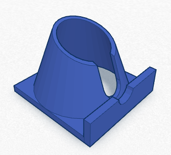
I have designed a small duct/bracket that I hope will work.  The intent is to cool the heat break, but keep the hot end hot.


I will post some pictures when I have it printed and installed.

Overheating Melzi Board

Although it has never happened before, Alfred just froze in mid-print.  This happened twice and it really seemed to be an issue with the CPU board components overheating.  They already run insanely hot in ambient air, but the have never just stopped operating.

As a temporary solution, I rigged up a old CPU fan to constantly blow on the board.  It definitely cooled the component, and the printer did not halt.

I think it may be wise to rig a permanent cooling solution for the motherboard.  Perhaps an enclosed case with with a 40mmx40mm fan.


Melted Bed Screw Terminal Block Connector

I notice that I had a melted terminal block where the bed heating wires are connected to the motherboard.

At first I thought I had possibly shorted the heater, but after some research it seems to be a common problem.  The apparent cause is loose wiring.

So, I have new screw connector and everything I need to fix the board.  The only thing is to be careful not to lift the pads on the PCB.

And Unknown Nozzle Width

I was so frustrated with my 0.2mm nozzle that when it clogged, I decided to try and drill out a larger size orifice.  While the task was easy, the result were a little off.  The extrusion amount was now much more pronounced.

My original problem was solved... as I expected, 0.2mm is too small.  It takes too high a pressure and temperature to be able to extrude effectively.

SO for no, I am experimenting with various nozzle sizes to get the best prints.

I will keep you posted.


Wednesday, February 10, 2016

More Fun To Be Had

While I continue to print bigger and better things on my Heacent 3DP02, I have learned quite a bit about 3D printing in general.

Temperature Is Important

Take for instance the temperature setting for the extruder hot end.  If it is set 5 degrees too low, the extruder will not put out enough material and you will get gaps and weak bonding between layers.


Just 5 degrees higher and the same model comes out like this...


By the same token, I had alot of trouble printing with the translucent PLA, because apparently it needs a much higher temperature.

Another problem I seem to have is temperature consistency.  The hot end temperature does oscillate by several degrees, so I will probably have to tune the PID values.  Again, because I do not know what "normal" is, I think something is fine... but it really isn't.

New Firmware

If I have to consider tuning my temperature PIDs, I may look again at upgrading the firmware on my printer.  The latest Marlin firmware has auto-tuning commands built right in to the firmware... as well as a bunch of other nice features.

The issue I have is whether I should (or can) upgrade any of the other software.  I have already upgraded to the latest version of Slic3r within the Repetier Host... I'm just not sure I can upgrade the Repetier host app.


Some parting shots of items I have printed...


Tuesday, January 26, 2016

Printing Stuff At Last

Well, I finally fixed enough problems with my 3D printer to actually start printing some useful (and fun) objects.


My most prolific issue was slipping of the X and Y axis under high torque situations.  It turns out the grub screws for the aluminum timing gear pulley were not nearly long enough to get a tight fit against the flat of the motor shaft.  Once I used some spare M3 bolts to tighten the pulley, I was good to go.

There are so many things I need to do and try it is hard for me to keep track...


  • I need to mount a 30mm x 30mm fan under the carriage to try and cool the heat break.
  • Problem - Gunk On Small Surfaces
  • Problem - Strings!
    • I need to test out various Extrusion Widths to see if they help with the current issue I have with gunk and strings on the prints
    • I need to calibrate and tune the hot end temp and PID
  • Print duct for main fan so that it blows more directly on the print
  • Calibrate X and Y (very accurately)


Thursday, January 21, 2016

The Debugging Continues

As I try to get my 3D printer into working order, I am finding out about things I need to work on.  The first problem is the cooling of the heat break just above the hot end.  I removed all the Kapton tape that was insulating the heat break as a first step.


The next step will be to re-direct the fan air flow to be over the heat break.  Temporarily, I think I will jimmy rig an adapter that will allow me to point the fan better.

Of course, the correct fix will be to put a small fan directly blowing on the tube.

The other thing I am looking into is upgrading the firmware on the printer,  I have a Melzi board that I believe will be able to run Marlin... an up to date firmware that seems to be the most popular.


Wednesday, January 20, 2016

Problems With My Hotend

I have been trying now to figure out an issue with so little extrusion coming from my 0.2mm nozzle.  The first problem I noticed was that the extruder feed was not moving very fast at all.  This led me to the firmware for the printer and the following changes.

I changed the E-steps setting in the firmware calibration from...


to this value...


And I finally was able to see some movement of the extruder motor during printing.

As a side note, I have learned that my hotend is not being properly cooled.  I need to cool the "heat break" and the print area, while now there is a fan blowing on the whole thing... even the heater block.


As soon as I am able, I will print a fan shroud that can cool both from the 40mm fan I currently have.